What is a Ripple Carry Adder?
A Ripple Carry Adder is a basic combinational circuit that adds two binary numbers using a series of full adders. Each full adder handles one bit and passes its carry output to the next stage. For a 4-bit adder, four full adders are used in series.
Key Concepts:
- The least significant bit (LSB) is added first, using an initial carry-in of 0.
- The carry “ripples” through each stage, affecting the next bit’s computation.
- The final output includes a 4-bit sum and a final carry-out.
Verilog Code: Ripple Carry Adder Using Structural Modelling
Full Adder Module
//Pantech e-learnig
// Full Adder – Structural Modeling
module full_adder(
input a,
input b,
input c,
output sum,
output cout);
wire w1, w2, w3;
xor (w1, a, b);
xor (sum, w1, c);
and (w2, c, w1);
and (w3, a, b);
or (cout, w2, w3);
endmodule
// 4-bit Ripple Carry Adder using Full Adders
module ripple_adder(
input [3:0] a,
input [3:0] b,
output [3:0] sum,
output co);
wire w1, w2, w3;
full_adder u1(a[0], b[0], 1’b0, sum[0], w1);
full_adder u2(a[1], b[1], w1, sum[1], w2);
full_adder u3(a[2], b[2], w2, sum[2], w3);
full_adder u4(a[3], b[3], w3, sum[3], co);
endmodule
Testbench
//Pantech e-learnig
// Testbench for Ripple Carry Adder
module ripple_adder_tb;
reg [3:0] a, b;
wire [3:0] sum;
wire co;
ripple_adder uut (
.a(a),
.b(b),
.sum(sum),
.co(co)
);
initial begin
$dumpfile(“dump.vcd”);
$dumpvars(0, ripple_adder_tb);
a = 4’b0000; b = 4’b0000; #10;
a = 4’b0001; b = 4’b0001; #10;
a = 4’b0011; b = 4’b0101; #10;
a = 4’b1111; b = 4’b0001; #10;
a = 4’b1010; b = 4’b0101; #10;
a = 4’b1111; b = 4’b1111; #10;
$finish;
end
endmodule
Simulation Output
View the waveform in GTKWave or ModelSim to confirm the correctness of each sum and carry output. Observe how carry bits ripple from one stage to the next.

Figure: Ripple carry adder simulation waveform output
FAQs for Ripple Carry Adder
Q1: What is a Ripple Carry Adder?
A circuit that adds two binary numbers using multiple full adders connected in series.
Q2: Why is it called “Ripple” Carry Adder?
Because the carry-out from one stage must propagate (ripple) through all later stages.
Q3: What is the main disadvantage of RCA?
It’s slower for large bit-widths due to sequential carry propagation delays.
Q4: How many full adders are needed for an n-bit RCA?
An n-bit RCA requires exactly n full adders.
Q5: Where is RCA used?
In simple ALU designs and applications where speed is not a major concern.
Conclusion
Ripple Carry Adders offer an easy-to-understand introduction to digital addition. Though not the fastest, their simplicity makes them suitable for learning and small-scale projects. Understanding RCA forms the basis for grasping more advanced adders like Carry Look-Ahead or Carry Select Adders.
Call to Action
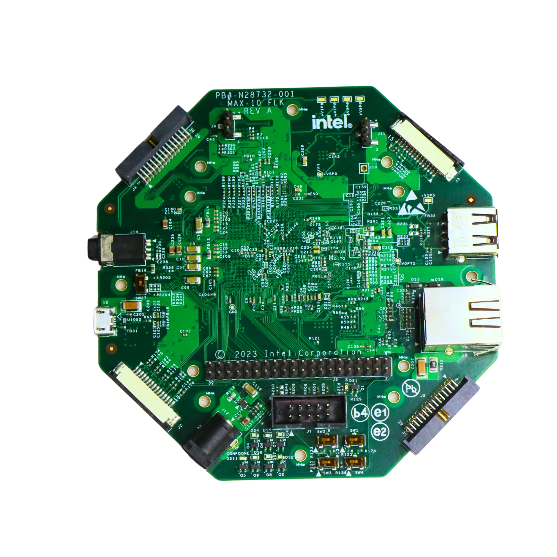
Try implementing this 4-bit Ripple Carry Adder on a MAX10 FLK FPGA board and observe how the carry ripples through each stage in real-time.
Looking to master all combinational and sequential circuits in Verilog? Explore our complete Verilog series—available exclusively on the Pantech eLearning platform.
Want hands-on experience?
Join our certified VLSI internship program at Pantech and work on live FPGA-based projects using Intel MAX10 boards, perfect for students, beginners, and aspiring embedded developers.
- All Projects
- Product