Core Sections
Concept Explanation
The XOR gate outputs 1 only when one input is different from the other. It is widely used in half-adders, full adders, and parity checkers.
Truth Table:
|
A |
B |
A XOR B |
|
0 |
0 |
0 |
|
0 |
1 |
1 |
|
1 |
0 |
1 |
|
1 |
1 |
0 |
Implementation
Verilog Design Code
// Pantech e-learning
// XOR gate using dataflow modeling
module xor_gate(
input a,
input b,
output y
);
assign y = a ^ b;
endmodule
Testbench Code
// Pantech e-learning
module xor_gate_tb;
reg a, b;
wire y;
xor_gate uut(
.a(a),
.b(b),
.y(y)
);
initial begin
$dumpfile(“dump.vcd”);
$dumpvars;
a = 1’b0; b = 1’b0;
#10 a = 1’b0; b = 1’b1;
#10 a = 1’b1; b = 1’b0;
#10 a = 1’b1; b = 1’b1;
#10 $finish;
end
endmodule
Results / Waveform Output
The waveform confirms that the output Y is high (1) only when A and B differ. The simulation was run using EDAPlayground, and the waveform was viewed using the integrated EPWave tool.

Figure: XOR gate
Applications
- Used in arithmetic circuits like half and full adders
- Key logic in parity generation and detection
- Useful in bitwise comparison systems
- Found in data transmission error checkers
- Crucial in cryptographic operations
Frequently Asked Questions (FAQs)
Q1: What is the key function of an XOR gate?
A1: It outputs 1 only when the two inputs are different.
Q2: How is XOR useful in arithmetic circuits?
A2: XOR computes the sum bit in half and full adders.
Q3: Can XOR be used for error detection?
A3: Yes, it’s commonly used in parity checking systems to detect single-bit errors.
Q4: What happens if one XOR input is 1 and the other is unknown (X)?
A4: The output becomes X because it depends on the undefined input.
Q5: How is XOR represented in Verilog?
A5: Using the ^ operator: assign y = a ^ b;
Conclusion
This guide demonstrated how to implement and test an XOR gate using Verilog with clear simulation steps and explanations. It also highlighted the practical importance of XOR gates in digital systems.
Call to Action (CTA)
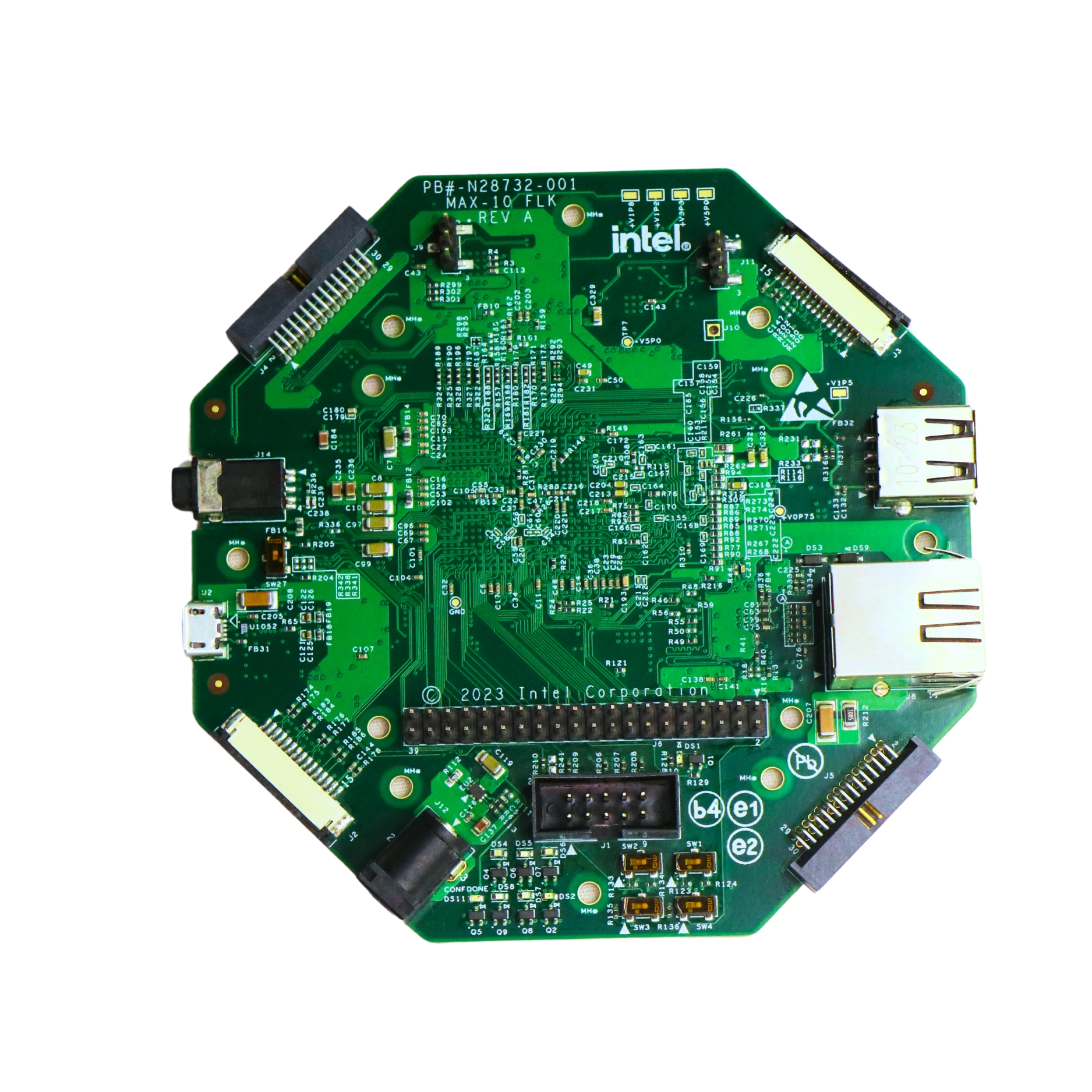
- Practice this project hands-on using the MAX10 FLK FPGA Development Kit available from Pantech eLearning.
- Interested in real-time digital logic implementation? Join our FPGA/VLSI Internship Program today.
- All Projects
- Product