Designing a Binary Adder-Subtractor in Verilog - Complete Implementation Guide
Description
Learn how to implement a versatile binary adder-subtractor circuit in Verilog. This guide covers the working principle, truth tables, Verilog code with testbench, and practical applications.
Introduction
Binary adder-subtractors are fundamental building blocks in digital systems, used in ALUs, processors, and arithmetic units. This tutorial covers:
- 2’s complement subtraction method
- Combined adder-subtractor logic
- Verilog implementation using dataflow modeling
- Complete testbench verification
Core Design
Circuit Principle
The circuit performs:
- Addition when control signal sub = 0
- Subtraction (using 2’s complement) when sub = 1
Truth Table
sub | A | B | Result |
0 | 0 | 0 | A+B |
0 | 0 | 1 | A+B |
1 | 0 | 0 | A-B (2’s comp) |
1 | 1 | 0 | A-B (2’s comp) |
Verilog Implementation
Main Module
module adder_subtractor(
input [3:0] a, b,
input sub, // 0=add, 1=subtract
output [3:0] sum,
output cout
);
wire [3:0] b_xor = b ^ {4{sub}}; // Invert for subtraction
assign {cout, sum} = a + b_xor + sub; // Add 1 for 2’s complement
endmodule
Testbench
module tb;
reg [3:0] a, b;
reg sub;
wire [3:0] sum;
wire cout;
adder_subtractor uut(a, b, sub, sum, cout);
initial begin
$monitor(“Time=%0t A=%b B=%b sub=%b → Sum=%b Cout=%b”,
$time, a, b, sub, sum, cout);
// Addition tests
sub = 0;
a = 4’b0001; b = 4’b0010; #10; // 1+2=3
a = 4’b1000; b = 4’b1000; #10; // 8+8=16 (overflow)
// Subtraction tests
sub = 1;
a = 4’b0101; b = 4’b0010; #10; // 5-2=3
a = 4’b0001; b = 4’b0011; #10; // 1-3=-2 (2’s comp)
$finish;
end
endmodule
Simulation Results/Output
Figure 1: Binary adder subtractor output log file
Figure 2: Binary adder subtractor output waveform
Frequently Asked Questions (FAQs)
Q1: Why do we XOR b with m in adder-subtractor?
A1: XORing b with m inverts b only when m = 1, enabling 2’s complement subtraction logic.
Q2: What does m control in a binary adder-subtractor?
A2: m selects the operation — addition when m = 0, subtraction when m = 1.
Q3: Why do we use m as the initial carry-in (cin)?
A3: To complete 2’s complement subtraction, we need to add 1 after inverting b, which is done by setting cin = 1.
Q4: What happens if the result is negative?
A4: The result appears in 2’s complement form, such as 1110 representing -2 in a 4-bit system.
Q5: Why is structural modelling used here?
A5: Structural modelling reflects real gate-level connectivity and helps understand circuit composition using modules like full adders.
View and simulate the full project here:
EDA Playground Simulation – Binary Adder-Subtractor
Conclusion
You’ve learned how to design a 4-bit binary adder-subtractor in Verilog using structural modeling. This design is ideal for understanding the logic of 2’s complement arithmetic and modular digital circuit construction. Structural modeling is widely used in real-world digital design for scalability and clarity.
Call to Action (CTA)
Try building this on your own FPGA or VLSI Lab Kit.
Join our VLSI Internship Program to explore more hands-on Verilog projects like this.
About Author:
A. Manikandan is an RTL Engineer at Pantech India Solutions Pvt. Ltd. With a strong passion for digital design ,FPGAs and ASIC bus protocols. he specializes in FPGA and hardware development, sharing insights to bridge the gap between academia and industry.
You can adjust the second line to reflect any specific expertise or areas of interest you wish to highlight!
Looking Ahead: Collaborate With Us
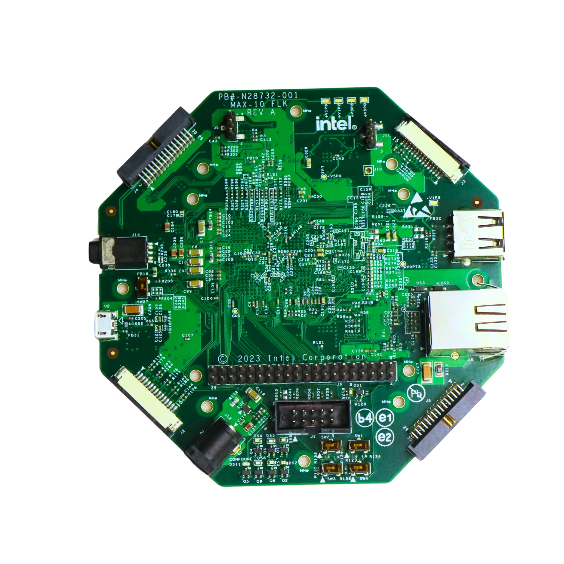
- Try building this Full Adder on the Intel MAX10 FLK FPGA board and visualize the simulation results in real-time.
- Want to build a complete multi-bit adder? Explore our beginner-friendly Verilog series at Pantech eLearning.
- Looking for hands-on training? Join our FPGA/VLSI Internship Program and take your digital design skills tothe next level!
- Email: sales@pantechmail.com
- Website: pantechelearning.com
- Exploring EV models & Battery Management Systems
- Deep dive into autonomous systems & Steer-by-Wire tech
Let’s innovate together—and prepare the next generation of tech leaders.
Digital Electronics
Digital electronics
click here
Boolean Algebra and Logic Gates.
click here...
Implementing and Simulating the OR Gate.
click here
Designing XOR Logic in Verilog
click here
Building the NOR Gate in Verilog
click here
Designing the NAND Gate.
click here
Designing a Half Adder in Verilog
click here
Building a Ripple Carry Adder in Verilog.
click here
Designing a 2x1 Multiplexer in Verilog
click here
Carry look ahead.
click here
Comparator in verilog.
click here
Decoder
click here
Designing a Binary Adder
click here

- All Projects
- Product