Designing a 2-Bit Magnitude Comparator in Verilog - Complete Implementation Guide Unlocking the Future of Semiconductor Design
Description
This comprehensive guide covers everything about designing a 2-bit magnitude comparator in Verilog – from truth table analysis to complete working code with testbench. Includes live EDA Playground simulation link for hands-on practice.
Introduction
Digital magnitude comparators are essential building blocks in computer systems, used everywhere from ALUs to memory address decoding. This tutorial provides a complete walkthrough of designing, implementing, and verifying a 2-bit comparator in Verilog HDL. We’ll cover:
- Detailed truth table analysis
- Dataflow modeling implementation
- Comprehensive testbench design
- Simulation verification
- Practical applications
- Live code example on EDA Playground
Understanding the 2-Bit Comparator Architecture
Functional Specifications
A 2-bit magnitude comparator takes two 2-bit binary numbers as inputs:
- A = A1 A0 (MSB to LSB)
- B = B1 B0 (MSB to LSB)
And produces three single-bit outputs:
- x = 1 when A > B
- y = 1 when A == B
- z = 1 when A < B
Complete Truth Table Analysis
A1 | A0 | B1 | B0 | x (A>B) | y (A=B) | z (A<B) | Description |
0 | 0 | 0 | 0 | 0 | 1 | 0 | Equal case (0 == 0) |
0 | 0 | 0 | 1 | 0 | 0 | 1 | 0 < 1 |
0 | 0 | 1 | 0 | 0 | 0 | 1 | 0 < 2 |
0 | 0 | 1 | 1 | 0 | 0 | 1 | 0 < 3 |
0 | 1 | 0 | 0 | 1 | 0 | 0 | 1 > 0 |
0 | 1 | 0 | 1 | 0 | 1 | 0 | Equal case (1 == 1) |
0 | 1 | 1 | 0 | 0 | 0 | 1 | 1 < 2 |
0 | 1 | 1 | 1 | 0 | 0 | 1 | 1 < 3 |
1 | 0 | 0 | 0 | 1 | 0 | 0 | 2 > 0 |
1 | 0 | 0 | 1 | 1 | 0 | 0 | 2 > 1 |
1 | 0 | 1 | 0 | 0 | 1 | 0 | Equal case (2 == 2) |
1 | 0 | 1 | 1 | 0 | 0 | 1 | 2 < 3 |
1 | 1 | 0 | 0 | 1 | 0 | 0 | 3 > 0 |
1 | 1 | 0 | 1 | 1 | 0 | 0 | 3 > 1 |
1 | 1 | 1 | 0 | 1 | 0 | 0 | 3 > 2 |
1 | 1 | 1 | 1 | 0 | 1 | 0 | Equal case (3 == 3) |
Verilog Implementation Using Dataflow Modeling
Module Definition
module magnitude_comparator(
input [1:0] a, // First 2-bit number (A1A0)
input [1:0] b, // Second 2-bit number (B1B0)
output x, // A > B
output y, // A == B
output z // A < B
);
Download
// Using Verilog relational operators
assign x = (a > b) ? 1’b1 : 1’b0;
assign y = (a == b) ? 1’b1 : 1’b0;
assign z = (a < b) ? 1’b1 : 1’b0;
// Alternative implementation using gate-level logic:
// assign x = (a[1] & ~b[1]) |
// (a[0] & ~b[1] & ~b[0]) |
// (a[1] & a[0] & ~b[0]);
// assign y = (a[1]~^b[1]) & (a[0]~^b[0]); // XNOR for equality
// assign z = ~x & ~y;
endmodule
Comprehensive Testbench Design
Testbench Module
module tb_magnitude_comparator;
reg [1:0] a, b;
wire x, y, z;
// Instantiate the comparator
magnitude_comparator uut (.a(a), .b(b), .x(x), .y(y), .z(z));
// Initialize inputs and monitor changes
initial begin
$display(“Time\tA\tB\t>\t=\t<“);
$monitor(“%0t\t%b\t%b\t%b\t%b\t%b”,
$time, a, b, x, y, z);
// Test all 16 possible combinations
a = 2’b00; b = 2’b00; #10;
a = 2’b00; b = 2’b01; #10;
a = 2’b00; b = 2’b10; #10;
a = 2’b00; b = 2’b11; #10;
a = 2’b01; b = 2’b00; #10;
a = 2’b01; b = 2’b01; #10;
a = 2’b01; b = 2’b10; #10;
a = 2’b01; b = 2’b11; #10;
a = 2’b10; b = 2’b00; #10;
a = 2’b10; b = 2’b01; #10;
a = 2’b10; b = 2’b10; #10;
a = 2’b10; b = 2’b11; #10;
a = 2’b11; b = 2’b00; #10;
a = 2’b11; b = 2’b01; #10;
a = 2’b11; b = 2’b10; #10;
a = 2’b11; b = 2’b11; #10;
$finish;
end
endmodule
Simulation Results and Verification
Figure 1: Comparator simulation output log file
Figure 2: Comparator simulation output waveform
The simulation should show correct comparison results for all 16 input combinations, with exactly one of x, y, or z high for each input pair.
Practical Applications
- CPU Design:
- Used in ALUs for branch comparisons
- Memory address range checking
- Digital Control Systems:
- Threshold detection
- Error checking circuits
- Communication Systems:
- Signal strength comparison
- Priority encoders
FAQs
Q1: How can I extend this to 4-bit or larger comparators?
A: Either cascade multiple 2-bit comparators or modify the code to handle wider inputs directly:
module comp_4bit(input [3:0] a, input [3:0] b, output x, y, z);
assign x = (a > b);
assign y = (a == b);
assign z = (a < b);
endmodule
Q2: What’s the difference between dataflow and behavioral modeling for comparators?
A: Dataflow (shown here) uses continuous assignments, while behavioral would use procedural blocks (always). Dataflow is generally more concise for simple combinational logic.
Q3: How do I implement this on actual hardware?
A: You can synthesize this code for FPGAs (Xilinx/Altera) or ASICs. The synthesis tool will optimize the logic gates.
Q4: Can I make a pipelined version for better timing?
A: Yes, by adding pipeline registers, though for 2-bit comparison it’s typically unnecessary.
Conclusion
This tutorial provided a complete implementation of a 2-bit magnitude comparator in Verilog, covering:
- Detailed truth table analysis
- Dataflow modeling implementation
- Comprehensive testbench design
- Simulation verification
- Practical applications
Try it yourself on EDA Playground:
2-Bit Magnitude Comparator Implementation
For hands-on learning:
- Modify the code to implement a 4-bit comparator
- Experiment with gate-level implementation (commented in code)
- Try adding a “greater than or equal” output
- Implement on FPGA hardware using our VLSI training kits
To dive deeper into digital design, check out our:
- Advanced Verilog Course
- FPGA Design Workshop
- VLSI Internship Program
About Author:
A. Manikandan is an RTL Engineer at Pantech India Solutions Pvt. Ltd. With a strong passion for digital design ,FPGAs and ASIC bus protocols. he specializes in FPGA and hardware development, sharing insights to bridge the gap between academia and industry.
You can adjust the second line to reflect any specific expertise or areas of interest you wish to highlight!
Looking Ahead: Collaborate With Us
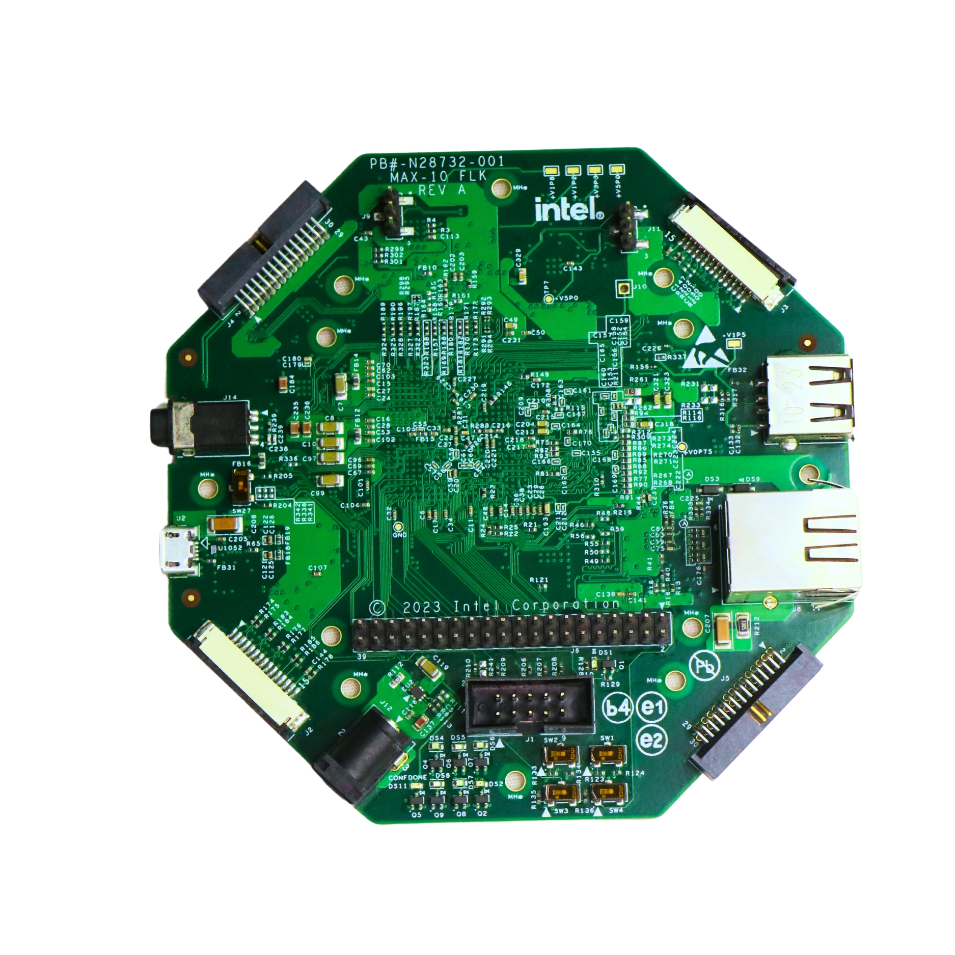
- Try building this Full Adder on the Intel MAX10 FLK FPGA board and visualize the simulation results in real-time.
- Want to build a complete multi-bit adder? Explore our beginner-friendly Verilog series at Pantech eLearning.
- Looking for hands-on training? Join our FPGA/VLSI Internship Program and take your digital design skills tothe next level!
- Email: sales@pantechmail.com
- Website: pantechelearning.com
- Exploring EV models & Battery Management Systems
- Deep dive into autonomous systems & Steer-by-Wire tech
Let’s innovate together—and prepare the next generation of tech leaders.
Digital Electronics
Digital electronics
click here
Boolean Algebra and Logic Gates.
click here...
Implementing and Simulating the OR Gate.
click here
Designing XOR Logic in Verilog
click here
Building the NOR Gate in Verilog
click here
Designing the NAND Gate.
click here
Designing a Half Adder in Verilog
click here
Building a Ripple Carry Adder in Verilog.
click here
Designing a 2x1 Multiplexer in Verilog
click here
Carry look ahead.
click here
Comparator in verilog.
click here
Decoder
click here
Designing a Binary Adder
click here

- All Projects
- Product