MATLAB SIMULINK
Internship 2025
Career-Based Complete MATLAB SIMULINK Internship Program. Get Insights into: Matlab, Designs and Control concepts with Project Implementation and Assignments. Stay Updated on Latest Industrial Updates.
1/ 2 Months
Online
8+ Live Projects
Dual Certification
Ultimate Step towards your Career Goals: Expert in MATLAB SIMULINK
Get ahead with the FutureTech Industrial Internship Program: gain hands-on experience, connect with industry leaders, and develop cutting-edge skills. Earn a stipend, receive expert mentorship, and obtain a certificate to boost your career prospects. Transform your future with practical, real-world learning today
Internship Benifits
Mentorship
Receive guidance and insights from industry experts.
Hands-on Experience
Gain practical skills in a real-world cutting-edge projects.
Networking
Connect with professionals and peers in your field.
Skill Development
Enhance your technical and soft skills.
Career Advancement
Boost your resume with valuable experience.
Certificate
Get a certification to showcase your achievements.
MATLAB SIMULINK Internship Overview
1. Single/Three Phase Rectifier using MATLAB
- Single-phase Rectifier: Converts single-phase AC to DC using diodes or thyristors (half-wave/full-wave).
- Three-phase Rectifier: Converts three-phase AC to DC using a six-diode bridge for smoother DC output.
- MATLAB/Simulink models these rectifiers and analyzes DC output, ripple, and efficiency.
2. Single/Three Phase AC Voltage Controller using MATLAB
- Single-phase Controller: Regulates voltage by adjusting the phase angle of the AC waveform.
- Three-phase Controller: Controls voltage by adjusting phase angles in all three phases.
- MATLAB simulates and optimizes voltage regulation for different loads.
3. DC-DC Converter using MATLAB
- Buck Converter: Steps down DC voltage.
- Boost Converter: Steps up DC voltage.
- Buck-Boost Converter: Steps up or down DC voltage.
- MATLAB/Simulink models converter circuits and optimizes performance like ripple and efficiency.
4. Inverter Design using MATLAB
- Converts DC to AC power.
- Square-Wave Inverter: Simple but with high distortion.
- Sine-Wave Inverter: Uses PWM for clean AC output.
- MATLAB/Simulink simulates inverter circuits and controls, analyzing efficiency and harmonic distortion.
Matrix Converter using MATLAB: A Matrix Converter (MC) directly converts AC to AC without an intermediate DC stage. MATLAB is used to design control algorithms, like Space Vector Modulation (SVM), for efficient phase commutation.
Multi-Level Inverter Design using MATLAB SIMULINK: A Multi-Level Inverter (MLI) reduces harmonics by generating multiple voltage levels. Simulink helps design the inverter using PWM and power switches to improve output quality.
Active Power Filter Design using MATLAB SIMULINK: An Active Power Filter (APF) compensates for harmonics and reactive power in a system. Simulink is used to model dynamic compensation using control algorithms like p-q theory.
Battery Charger Design using MATLAB SIMULINK: A battery charger manages charging profiles (constant current, constant voltage). Simulink is used to design converters and control loops to efficiently charge batteries.
Speed Control of DC Motor Using Chopper:
A chopper (DC-DC converter) is used to vary the voltage supplied to a DC motor, allowing efficient speed control. In Simulink, the chopper’s switching controls the motor’s speed via PWM.Simulink Based Speed Control of Induction Motor Using VSI Fed Inverter:
A Voltage Source Inverter (VSI) converts DC to AC to control the frequency and voltage supplied to an induction motor, enabling speed control. This is modeled in Simulink for applications like industrial drives.Simulink Based Speed Control of BLDC Motor Using Chopper:
A chopper regulates the voltage to a BLDC motor, adjusting speed via PWM. This method is efficient and used in applications like electric vehicles and drones.Simulink Based Speed Control of PMSM Motor Using Chopper:
A chopper controls the voltage to a PMSM, enabling precise speed control. It is used in high-performance applications like robotics and electric vehicles, often combined with advanced control techniques like Field Oriented Control (FOC).
Gate Driver Design for IGBT/MOSFET: Circuits that control the switching of IGBTs/MOSFETs in high-power applications, ensuring proper gate voltage and current for efficient operation.
AD/DC Current/Voltage/Speed Measurement Circuit Design: Circuits to measure electrical parameters like current, voltage, and motor speed using sensors for monitoring and control.
Inductor/Transformer/High-Frequency Transformer Design: Designing components for energy storage and voltage transformation in power electronics, focusing on factors like core material and frequency response.
Arduino Programming using MATLAB: Using MATLAB to program Arduino for controlling sensors and actuators in embedded systems, with simulation and data analysis.
Buck/Boost Converter Design with Arduino: Designing and controlling DC-DC converters (buck/boost) with Arduino, using PWM to regulate output voltage.
Wind Energy Power System Design: Designing systems that convert wind energy into electrical power, integrating turbines, generators, and storage solutions.
Smart Energy Meter System Design using Arduino: Designing energy meters with Arduino to measure and monitor electricity consumption, with remote data logging and control.
Three-Phase Induction Motor Fault Diagnosis: Techniques to detect faults in three-phase motors, using sensors and diagnostic algorithms for early failure detection.
TI DSP Programming using MATLAB: Developing signal processing algorithms in MATLAB and implementing them on Texas Instruments DSPs for applications like audio and communications.
SMPS Design Calculations and Fabrication: Calculating and selecting components for efficient switch-mode power supplies (SMPS) and fabricating the design for power conversion applications.
Fuzzy Logic Controller-based MPPT Charge Controller: Uses a fuzzy logic controller to optimize the power extraction from solar panels by adjusting the operating point for maximum efficiency, handling uncertainties without precise models.
Vector Controlled Induction Motor using Simulink: Implements Field-Oriented Control (FOC) to precisely control an induction motor’s speed and torque using Simulink, improving motor performance and efficiency.
Hardware Design for Arduino-based Speed Control of Induction Motor: Uses an Arduino and PWM signals to control the speed of an induction motor, with sensors providing feedback for accurate speed regulation.


Looking for in-depth Syllabus Information? Explore your endless possibilities in MATLAB SIMULINK with our Brochure!
share this detailed brochure with your friends! Spread the word and help them discover the amazing opportunities awaiting them.
Project Submission: Example Output Screenshots from Our Clients
Take a look at these sample outputs crafted by our clients. These screenshots showcase the impressive results achieved through our courses and projects. Be inspired by their work and visualize what you can create!


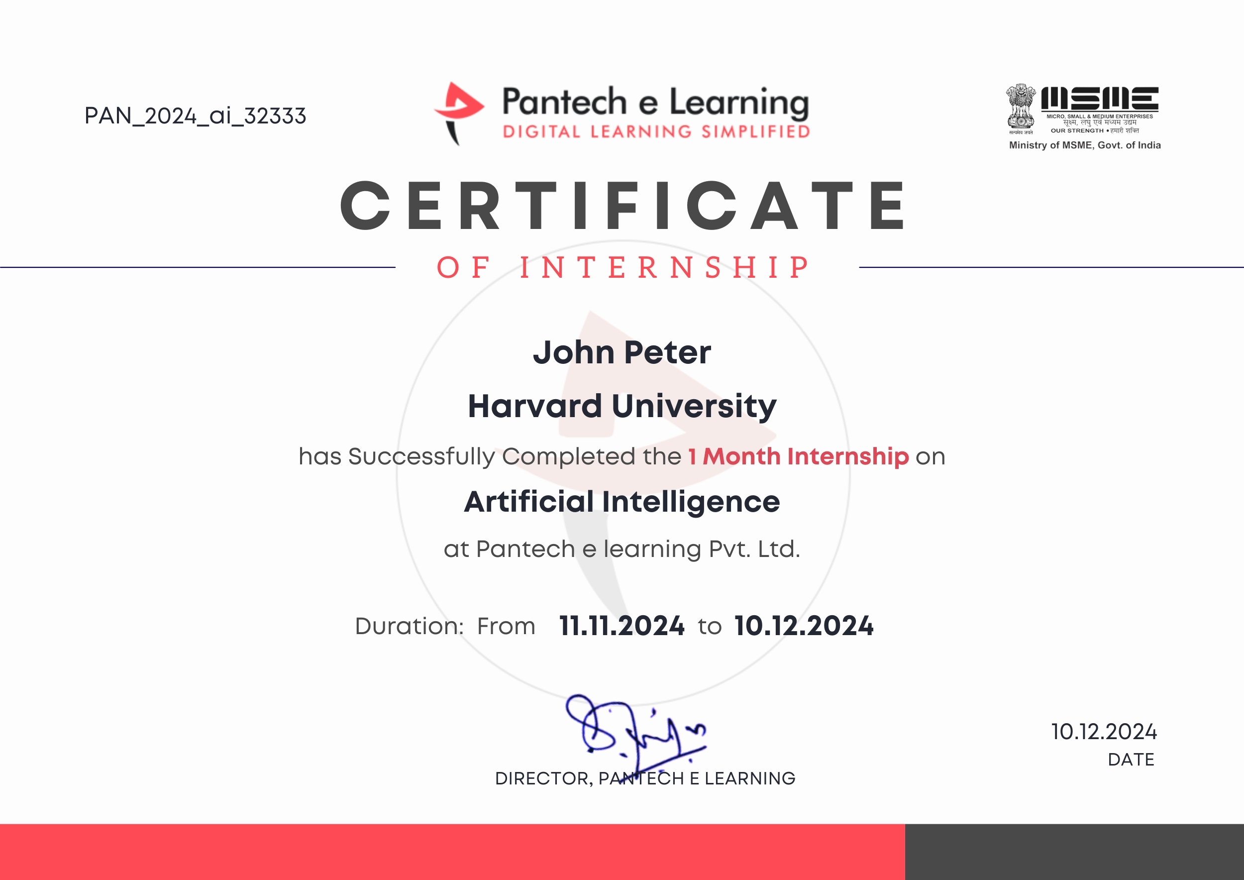
Dual Certification: Internship Completion & Participation
Earn prestigious Dual Certification upon successful completion of our internship program. This recognition validates both your participation and the skills you have honed during the internship


How does this Internship Program Work?
Step 1 Enroll in the Program
- Get a Mentor Assigned
- Presentations & Practice Codes
- Learn at your Flexible Time
- Apprehend the concepts
Step 2 Project Development
- Implement Skills Learn
- Develop Projects with assistance
- Get Codes for Reference
- Visualise the Concepts
Step 3 Get Certified
- Certificate of Internship
- Project Completion Certificate
- Share on social media
- Get Job Notifications
Choose Your Plan fit your needs
Master the Latest Industrial Skills. Select a technology domain & kick off your Internship immediately.
1 Month
₹1999/-
₹999/-
- Internship Acceptance Letter
- 90 Days from the date of payment
- 4 LIVE intractive Mastermind Sessions
- 4+ Capstone Projects & Codes
- Full Roadmap
- Internship Report
- 1 Month Internship Certificate
2 Month
₹3299/-
₹1899/-
- Internship Acceptance Letter
- 180 Days from the date of payment
- 4 LIVE interactive Mastermind Sessions
- 12+ Capstone Projects & Codes
- Full Roadmap
- Internship Report
- Participation Certificate
- 2 Month Internship Certificate
Our Alumni Employers
Curious where our graduates make their mark? Our students go on to excel in leading tech companies, innovative startups, and prestigious research institutions. Their advanced skills and hands-on experience make them highly sought-after professionals in the industry.


EXCELLENTTrustindex verifies that the original source of the review is Google. I recently completed my Python internship under the guidance of Mentor poongodi mam We learnt so many new things that developed my knowledge.this experience is good to learnTrustindex verifies that the original source of the review is Google. I completed my python internship guidance of mentor poongodi mam. She thought us in friendly qayTrustindex verifies that the original source of the review is Google. Poongodi mam done very well She took the class very well When we ask any doubt without getting bored she will explain,we learned so much from mam,marvelousTrustindex verifies that the original source of the review is Google. I have handled by poongodi mam.domain python intership...was goodTrustindex verifies that the original source of the review is Google. I recently completed Python internship under the guidance of poongodi mam who excelled in explaining concepts in an easily understandable wayTrustindex verifies that the original source of the review is Google. Fantastic class we were attended..we got nice experience from this class..thank you for teaching python mam...Trustindex verifies that the original source of the review is Google. -The course content was well-structured - I gained valuable insights into microcontrollers, sensors, and programming languages- The workshop was informative, interactive, and challenging, pushing me to think creatively. Ms Jimna our instructor her guidance and feedback helped me overcome obstacles and improve my skills.Trustindex verifies that the original source of the review is Google. The learning experience was really worth since more than gaining just the knowledge all of the inputs were given in a friendly and sportive manner which then made it a good place to learn something with a free mindset... 👍🏻Trustindex verifies that the original source of the review is Google. I recently completed my full stack python intership under the guidance of mentor Gowtham,who excelled in explaining concepts in an easily understand mannerTrustindex verifies that the original source of the review is Google. Gowtham-very interesting class and I learning so many things in full stack python development and I complete my internship in Pantech e learning and it is useful for my career
FAQ
How do I use MATLAB scripts to enhance my Simulink model?
MATLAB scripts can be used in conjunction with Simulink to control simulations, analyze results, and automate tasks:
- You can use MATLAB scripts to modify block parameters dynamically.
- MATLAB functions can read simulation results (such as voltage or current waveforms) and analyze or visualize them further.
- You can create custom scripts for optimizing circuit designs, running parameter sweeps, or automating repetitive tasks.
Can I perform transient simulations in Simulink?
Yes, Simulink supports transient simulations, which means you can analyze time-varying systems. Electrical circuits with transient components like capacitors, inductors, and switching devices can be modeled to observe how voltages, currents, and other parameters evolve over time.
How do I simulate power electronics circuits in Simulink?
Simulink, along with the Simscape Electrical toolbox, provides blocks for modeling power electronics circuits, such as:
- Switching devices (e.g., MOSFETs, IGBTs)
- Rectifiers (AC to DC conversion)
- Inverters (DC to AC conversion)
- Converters (DC-DC or AC-DC conversion)
For switching circuits, use the Power Electronics block library, which lets you design systems like DC-DC converters, PWM inverters, and power amplifiers. You can also include controllers for managing switching logic.
How do I model an electrical motor in Simulink?
Simulink offers a variety of blocks for electrical motors, including:
- DC Motors: You can use the DC Machine block from the Simscape Electrical library.
- AC Motors: Models such as the Permanent Magnet Synchronous Machine (PMSM) or induction motors can be found in Simscape Electrical Specialized Power Systems.
- Synchronous Motors: These can be modeled using the “Synchronous Machine” block.
You can connect these motor blocks to a power supply, controllers, and load elements to simulate their operation under different conditions.
What is the difference between Simulink and Simscape Electrical?
Simulink is the general modeling and simulation environment, while Simscape Electrical is a specialized toolbox within Simulink designed specifically for electrical modeling. Simscape Electrical provides dedicated blocks for power systems, circuits, machines, and other electrical components, allowing for more efficient and realistic simulations in electrical design.
How do I simulate a circuit with dynamic components in Simulink?
Once your circuit is created using appropriate Simscape Electrical blocks, you can configure simulation parameters such as time duration, step size, and solver settings. To simulate, simply click the “Run” button and observe the system’s response in terms of voltage, current, or other electrical parameters.
You can visualize results using Scope blocks, Display blocks, or even export data to MATLAB for further analysis.
Start Your Tech Journey Today
Sign Up for Exclusive Resources and Courses Tailored to Your Goals!
© 2025 pantechelearning.com

